I had a simple question when I first started tinkering with electronics. I had a breadboard, a few components, and my laptop sitting right there. Why drag out a bench power supply when I could just use USB? It turns out you can, but there are three very different ways to do it and they are not equally safe or convenient.
This is what I figured out after going through each method. The short version: buy the MB102 module and stop thinking about it. But understanding why that is the right answer is actually worth knowing.
Each approach has a different risk profile
Before going through these, one thing to understand is what you are actually dealing with. Every USB port on your laptop outputs 5V. What varies is how much current it will deliver before either the port shuts down or something breaks. USB 2.0 caps at 500mA. USB 3.0 gives you up to 900mA. Those numbers matter more than most beginners realise.
MB102 Breadboard Power Supply Module
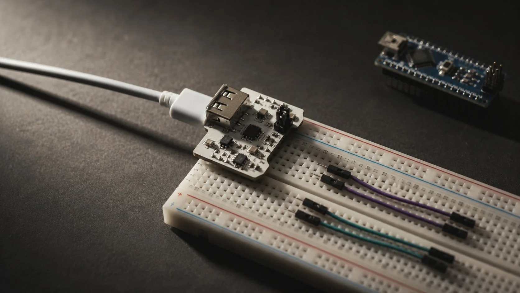
This is a small module specifically designed for breadboards. It slots directly into the power rails at the end of your breadboard, takes USB input from your laptop, and delivers either 3.3V or 5V depending on how you set a small jumper. It has onboard voltage regulators so what reaches your circuit is clean and stable, not the slightly noisy 5V that comes raw off USB. The better modules also include short-circuit protection, which means if you wire something wrong and create a dead short, the module shuts down instead of your laptop port taking the hit. You can find the MB102 for around 80 to 150 rupees in India, sometimes less in packs of five.
✓ Recommended — clean voltage, protected outputArduino or ESP32 as a Power Source
If you are already using a microcontroller in your project, you do not need any additional hardware at all. Connect the Arduino or ESP32 to your laptop via its regular USB cable, then run a jumper wire from the 5V pin on the board to the positive rail of the breadboard, and another from the GND pin to the negative rail. The microcontroller board already has its own voltage regulator and handles the USB interface safely. The limitation here is current: the 5V pin on an Arduino Uno is typically rated to around 400mA, which is enough for sensors and small ICs but nothing power-hungry. Also, this only works if a microcontroller is already part of your circuit. If you are just prototyping passive components or op-amps, it adds unnecessary complexity.
● Good if you already need the microcontrollerStripped USB Cable
This is the fallback when you have no module and no microcontroller. Take an old USB cable you do not mind destroying, cut off one end, strip the outer insulation, and you will find four wires inside. Red is +5V, black is ground, green and white are data lines. Ignore the data wires. Solder or twist solid-core jumper wires onto the red and black leads, insulate carefully, and connect them to your breadboard rails. It works, but there is nothing between your laptop port and the breadboard. No regulation, no current limiting, no protection. A short circuit goes straight to the USB port. I have done this in a pinch. I would not make it a regular habit.
⚠ Works, but no protection layerThe current limits are more important than the voltage
Most people focus on voltage when they think about power supplies. With USB-powered breadboard projects, current is actually the thing to watch. 5V is fixed. Current is what varies depending on what your circuit draws, and what your USB port is willing to supply before it gives up.
A USB 2.0 port at 500mA sounds like plenty for a small project. It is, for most sensor-based circuits, logic gates, LEDs with resistors, small displays. Where it goes wrong is when people try to drive motors directly off the breadboard, or wire up a string of LEDs without calculating the total current draw. DC motors can pull ten times their rated current on startup. Even a modest servo can hit 600mA under load. These are the things that cause USB ports to shut down, or worse, fail quietly over time.
If your component's datasheet mentions current draw above 200mA, power it separately. Do not fight the USB port over who gets to supply that current. USB is for logic-level stuff. Anything with a motor or a coil needs its own supply.
The other thing worth keeping in mind is to never modify a live circuit. Always unplug the USB cable before moving jumper wires, swapping components, or adding anything to the breadboard. This sounds obvious but it is the kind of thing you stop doing after your first few sessions when nothing has gone wrong yet. And then one day you accidentally bridge two pins while the circuit is live and the port shuts down and you spend an hour wondering what happened.
ComparisonWhich method to pick
| Method | Cost | Voltage Options | Protection | Best For |
|---|---|---|---|---|
| MB102 Module | ~Rs. 100 | 3.3V or 5V | Short-circuit + regulated | Any breadboard project |
| Arduino / ESP32 | Already owned | 3.3V and 5V pins | Regulated via board | Projects using a microcontroller |
| Stripped USB cable | Zero | 5V only (unregulated) | None | Emergency use only |
One optional addition that is worth knowing about: if you are worried about protecting your laptop's actual USB port, plug your power cable into a cheap external USB hub instead of directly into the machine. If something goes very wrong on the breadboard side, the hub absorbs the damage rather than your laptop's mainboard. Hubs are replaceable for a few hundred rupees. Laptop USB controllers are not.
Rs. 100 and an MB102 module solves this cleanly
The MB102 costs almost nothing, slots straight into your breadboard, gives you selectable voltage, and puts a protection layer between your circuit and your laptop. It is not a sophisticated piece of hardware but it is exactly the right tool for this job. Buy a few, keep them in your parts box, and stop worrying about it.
The stripped cable method is not something I am telling you to never use. It is useful to understand how it works. But for anything you plan to use more than once, or any project where you are still figuring out the circuit, use the module. The cost difference between the methods is trivial. The peace of mind is not.